Working principle:
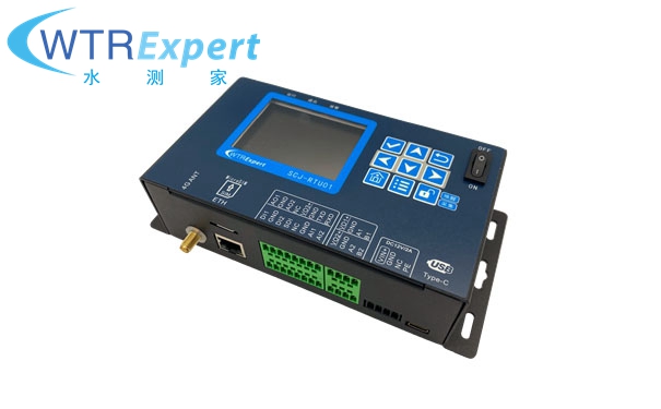
SCJ-RTU01 telemetry terminal is a low-power IoT data acquisition terminal with integrated 4G DTU. It is equipped with a 2.8-inch TFT LCD display, supports flow, water level, water quality, and meteorological data acquisition and transmission, and has a built-in large-capacity memory that can meet 3 years of data storage needs. It also supports remote configuration and upgrade functions to reduce the difficulty of customer installation and use. It supports Ethernet communication, NBIOT, and extended support for lora and Beidou communications.
Product images:

Features
n integrated 4G DTU, no external DTU required for communication;
n with a 2.8-inch TFT display and operation buttons for easy on-site debugging;
nsupport 512MB SD card storage (one piece of data per minute can be stored for 3 years);
n TYPE-C USB interface, convenient for connecting to computer;
nmultiple 485 and RS232 interfaces;
n 2-channel 4-20mA output and 2-channel 4-20mA analog acquisition interface;
n 2-way pulse/switch signal acquisition;
n local/remote configuration upgrade and historical data re-issuance function;
nlow standby power consumption;
n 4 central stations to send data simultaneously (4 central stations send data at the same time);
n 4 central stations to select different communication protocols to communicate with 4 central stations;
n rapid customization of communication protocols and sensor acquisition protocols;
Basic parameters :
1. Hardware interface: 2 RS485 interfaces, 1 232 interface, 2 switch inputs, 2 4-20mA analog outputs, 1 USB interface, 1 Ethernet interface.
2. Transmission mode: support GPRS, GSM, wired Ethernet data transmission, external lora, WIFI, Beidou.
3. Transmission interval: configurable (default five minutes) Collection interval: configurable (default five minutes)
4. Sensor type: water level meter, flow meter, water quality sensor, meteorological sensor, etc.
5. Flow calculation method: flow rate converted to water level, flow rate converted to gate level, flow rate converted to fixed weir.
6. Storage capacity: 512MB by default (can be expanded to a larger size), one piece of data can be stored per minute, and can be stored for no less than three years.
7. Supply voltage: 6-24V
8. Standby current: <0.6mA 12VDC
9. Working current: <5.5mA 12VDC (excluding sensor)
10. Data export method: USB local export or remote platform export. Data reissue: If the device has no signal or is disconnected, the data of at least three months can be cached and reissued.
11. Central Station: Send data to multiple central stations and ports at the same time. Three central stations are supported by default, and each central station has no less than 2 ports.
12. Working temperature: -30-70℃
13. The IoT card includes 1 year of data traffic, 100M per month, and customers can recharge it themselves after 1 year.
Other parameters :
Power supply range | DC 12V/24V 2A (limit DC 6-28V) usually DC12V 24W power supply |
Working current | <5.5 mA @ DC12V 25℃ ① |
Standby current | <0.6mA @ DC12V 25℃ ① |
Operating temperature | -30℃-70℃ |
Storage temperature | -35℃-75℃ |
RF Conducted Susceptibility | LTE FDD B1/B3/B5/B8/B34/B38/B39/B40/B41 <-99dBm ② |
RF output power | LTE FDD B1/B3/B5/B8 -44dBm ~ 23dBm (±2dBm) LTE TDD B34/38/B39/B40/B41 -42dBm ~ 23dBm (±2dBm) ② |
Maximum output current | <2A @DC12V (the total current output to the sensor cannot exceed 2A) |
SIM card type | MicroSIM (all network 4G SIM card) |
Display | 2.8 inch TFT LCD 320*240 resolution |
Antenna interface | SMA external thread inner hole (use internal thread inner needle 4G antenna) |
Transmission method | Ethernet or 4G, customizable 2G, or external lora, WIFI, Beidou communication |
Interface Description :
Logo | type | illustrate |
4G ANT | Antenna input | SMA external thread inner hole interface, external connection to 4G antenna with internal thread inner pin |
ETH | Ethernet | Ethernet interface (customized support) |
SIM | SIM slot | Using Micro SIM Card |
AO1 | Analog output | Active 4-20mA analog output interface 1 |
GND | Negative pole of power supply | |
AO2 | Analog output | Active 4-20mA analog output interface 2 |
NC | Leave empty | |
VO3+ | Power Output | Controllable power output 3, used for sensor power supply, voltage = input voltage - 0.5V |
GND | Negative pole of power supply | |
TXD | RS232-TXD | |
RxD | RS232-RXD | |
DI1 | Digital/Pulse Input | Tipping bucket rain gauge (passive pulse signal) |
GND | Negative pole of power supply | |
DI2 | Digital/Pulse Input | Keep the door detection |
SDI | SDI-12 Interface | SDI-12 bus interface (acquisition interface) |
NC | Leave empty | |
GND | Negative pole of power supply | |
AI1 | Analog input | 4-20mA analog acquisition interface 1 |
AI2 | Analog input | 4-20mA analog acquisition interface 2 |
VO1+ | Power Output | Controllable power output 1, used for sensor power supply, voltage = input voltage - 0.5V |
GND | Negative pole of power supply | |
A1 | RS485 bus | RS485 channel 1 bus A (D+) |
B1 | RS485 bus | RS485 channel 1 bus B (D-) |
VO2+ | Power Output | Controllable power output 2, used to power the sensor, voltage = input voltage - 0.5V |
GND | Negative pole of power supply | |
A2 | RS485 bus | RS485 channel 2 bus A (D+) |
B2 | RS485 bus | RS485 channel 2 bus B (D-) |
VIN+ | Power Input | Equipment working power supply DC12V/24V power input |
GND | Negative power input | Negative pole of the equipment working power input |
NC | Leave empty | |
PE | Ground terminal | Lightning protection grounding terminal |
Note: When using 4-20mA output, please ensure that the power supply voltage is above 10V (DC 12V power supply is recommended) ;
Application scenarios :
It can be widely used in various water conservancy information construction fields, such as remote measurement and control of hydrology, water resources, water environment, water pollution, mountain torrents, reservoir safety, and dam safety.
On-site case :

Interface function diagram :

Schematic diagram of common system composition :


